Choosing a DC motor gear ratio can look simple on paper. In practice, it determines whether a machine starts smoothly or stalls beside the workbench. This 2026 guide explains how to choose the right gear ratio for dc motor applications with practical engineering judgment, not guesswork.
Dr. Kevin Craig, a respected mechatronics educator, puts the core principle plainly: “A gear train trades speed for torque; it does not create power.” That idea should guide every selection. A higher ratio increases output torque and reduces speed. A lower ratio preserves speed but may struggle with heavy loads. The correct choice depends on load weight, wheel diameter, operating time, motor speed, available current, and required acceleration.
Begin with the real load, not the catalog’s ideal number. Measure starting resistance, incline angle, friction, and the force needed to move the mechanism. Then compare the motor’s continuous torque with the reflected load torque. Leave practical safety margin. Around 20% to 30% is often sensible, though demanding systems may need more. Efficiency, backlash, noise, and gearbox temperature also matter. A ratio that works for ten seconds may fail after ten minutes.
There is no perfect ratio.
A first calculation can be wrong. I have seen small motors overheat because designers trusted stall torque and ignored duty cycles. Select a ratio that supports reliable starting, steady operation, and controlled stopping. Confirm it with testing, current measurements, and temperature checks. Real machines reveal details that spreadsheets miss.
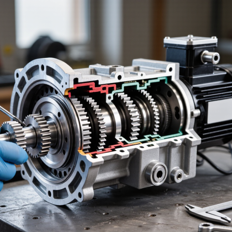
Understanding DC Motor Gear Ratios and Their Purpose
Understanding DC Motor Gear Ratios and Their Purpose
A DC motor gear ratio controls the balance between speed and torque. A 20:1 ratio means the motor turns twenty times for each output shaft revolution. The gearbox reduces speed and increases usable turning force. This matters when a small motor must move a heavy load.
For example, a motor spinning at 3,000 revolutions per minute may produce about 150 output revolutions with a 20:1 ratio. Real output speed will be lower under load. Friction, gear efficiency, and voltage changes affect performance. The available torque also depends on the motor’s current limit. More torque is not free.
In practical testing, I check startup behavior, not only running speed. A conveyor may need strong torque when fully loaded. A 10:1 ratio could stall it, while a 50:1 ratio might move too slowly. Measure the required load, shaft speed, duty cycle, and stopping demands. Leave some torque margin for dust, temperature, and wear. A first estimate is rarely perfect. I once selected a ratio from running torque alone, then found the motor failed during startup. That mistake showed why measured acceleration matters more than a neat calculation. Also consider backlash, noise, and gearbox life. A low ratio may feel responsive, but a higher ratio can provide steadier control.
2026 Top Guide: How to Choose the Right DC Motor Gear Ratio?
Gear reduction lowers output speed while increasing available torque. The chart below uses a 3,000 RPM DC motor with 0.20 N·m input torque. Values are calculated from the ideal relationships: output speed = motor speed ÷ gear ratio, and output torque = motor torque × gear ratio.
A higher gear ratio is suitable when the application needs more torque and slower movement. A lower ratio is preferable when higher output speed is more important. Real systems produce slightly less torque because of gearbox friction and efficiency losses.
Defining Speed, Torque, Load, and Operating Requirements
2026 Top Guide: How to Choose the Right DC Motor Gear Ratio?
Choosing a DC motor gear ratio begins with the required output speed. Measure the load’s actual operating speed, not only its advertised maximum. A 10:1 ratio can reduce motor speed by roughly ten times while increasing torque before efficiency losses. For example, a 3,000 rpm motor may deliver about 300 rpm at the gearbox output. Real results vary.
Torque matters just as much. Record the continuous load, starting load, and sudden resistance during operation. A conveyor carrying 8 kilograms may need much more starting torque than running torque. Include friction, slope, pulley size, and load inertia. A useful estimate is output torque equals motor torque multiplied by ratio and efficiency. Leave practical headroom.
Do not size the ratio from one perfect test. My first estimate is often wrong. A gearbox can meet speed targets but overheat during repeated starts. Check the duty cycle, available voltage, noise, backlash, and mounting space. Short bursts and continuous operation need different choices. Test the assembly with the real load for several cycles. Watch temperature, current, acceleration, and stopping behavior. A spreadsheet cannot reveal every vibration or stall. Small adjustments may improve control, but excessive reduction can make the system slow and inefficient.
2026 Top Guide: How to Choose the Right DC Motor Gear Ratio? – Defining Speed, Torque, Load, and Operating Requirements
| Application Profile |
Typical Output Speed |
Typical Output Torque |
Suggested Gear Ratio Range |
Recommended Gear Type |
Primary Design Priority |
| High-speed fan or blower |
1,000–3,000 rpm |
0.02–0.20 N·m |
1:1–5:1 |
Spur or helical |
Efficiency, noise, and balance |
| Conveyor roller |
30–300 rpm |
0.5–15 N·m |
5:1–50:1 |
Helical or planetary |
Continuous duty and starting torque |
| Small lifting mechanism |
5–80 rpm |
5–80 N·m |
20:1–150:1 |
Worm or planetary |
Holding load, safety, and thermal capacity |
| Robotic joint or actuator |
10–200 rpm |
1–40 N·m |
10:1–100:1 |
Planetary or harmonic-style reducer |
Backlash, precision, and response |
| Wheel drive or mobile platform |
50–600 rpm |
2–60 N·m |
5:1–40:1 |
Planetary or spur |
Shock resistance and acceleration |
| Positioning table |
1–100 rpm |
0.5–30 N·m |
20:1–200:1 |
Low-backlash planetary |
Repeatability and stiffness |
Gear Ratio Selection and Calculation Reference
| Design Parameter |
Formula or Guideline |
Example Value |
Selection Meaning |
| Required gear ratio |
Ratio = Motor speed ÷ Required output speed |
3,000 ÷ 100 = 30:1 |
A 30:1 reduction is required before considering losses and available products. |
| Output speed |
Output speed = Motor speed ÷ Gear ratio |
3,000 ÷ 30 = 100 rpm |
Higher ratios reduce speed and generally increase available torque. |
| Ideal output torque |
Torque = Motor torque × Gear ratio |
0.40 × 30 = 12 N·m |
This is theoretical torque before gearbox efficiency and safety margin. |
| Estimated real output torque |
Torque = Motor torque × Ratio × Efficiency |
0.40 × 30 × 0.85 = 10.2 N·m |
Use measured or catalog efficiency at the intended load and speed. |
| Required motor torque |
Motor torque = Load torque ÷ (Ratio × Efficiency) |
10 ÷ (30 × 0.85) = 0.392 N·m |
The motor should provide more than the calculated value after applying a margin. |
| Safety factor |
Design torque = Required torque × Safety factor |
10 × 1.5 = 15 N·m |
A factor of 1.25–2.00 is commonly considered, depending on shock and uncertainty. |
Operating Requirement Checklist
| Requirement |
What to Measure or Confirm |
Why It Affects Ratio Selection |
Practical Recommendation |
| Speed |
Minimum, nominal, and maximum output rpm |
The ratio determines the output speed range and motor operating point. |
Select a ratio that keeps the motor within its efficient speed range at nominal load. |
| Continuous torque |
Torque required during normal operation |
Continuous torque determines motor heating and gearbox thermal loading. |
Verify both motor rated torque and gearbox continuous torque. |
| Peak or starting torque |
Acceleration, stall, jam, and breakaway torque |
Short-term overloads can damage teeth, shafts, couplings, or motor windings. |
Check peak torque duration and frequency, not only the average value. |
| Load inertia |
Rotational inertia reflected to the motor shaft |
High reflected inertia can cause slow response, overshoot, and unstable control. |
Use a reducer to match inertia where appropriate, while checking backlash and torsional stiffness. |
| Duty cycle |
Operating time, rest time, and cycle frequency |
A ratio that works intermittently may overheat during continuous operation. |
Size the system for RMS torque and the actual duty cycle. |
| Backlash |
Allowable angular movement when reversing direction |
High backlash reduces positioning accuracy and can create impact during reversal. |
Choose low-backlash gearing for precision motion and closed-loop control. |
| Environment |
Temperature, dust, moisture, shock, and mounting orientation |
Environmental conditions affect lubrication, sealing, cooling, and service life. |
Confirm allowable temperature, enclosure rating, lubrication method, and shock capacity. |
Common Gear Ratio Choices: Advantages and Limitations
| Ratio Range |
Typical Result |
Advantages |
Potential Limitations |
| 1:1–5:1 |
Very high output speed with limited torque multiplication |
High efficiency, low size, and fast response |
Limited ability to handle high load torque |
| 5:1–20:1 |
Moderate speed reduction and torque increase |
Good balance of speed, torque, and efficiency |
May require multiple gear stages at the upper end |
| 20:1–100:1 |
Low output speed with substantial torque multiplication |
Suitable for conveyors, actuators, and lifting systems |
More heat, backlash, size, and efficiency loss |
| 100:1–200:1 or higher |
Very low speed and high theoretical torque multiplication |
Useful for slow positioning and high-load mechanisms |
Lower efficiency, slower response, greater wear, and possible self-locking behavior |
Key selection rule: Choose the lowest gear ratio that achieves the required output torque and speed while keeping the motor, gearbox, and thermal system within their continuous and peak operating limits. Always validate the final selection using actual load, acceleration, duty cycle, efficiency, backlash, and environmental conditions.
Calculating the Ideal Gear Ratio for Your Application
2026 Top Guide: How to Choose the Right DC Motor Gear Ratio?
Calculating the ideal gear ratio starts with speed, torque, and duty cycle. Use this basic equation:
gear ratio = motor speed ÷ required output speed
For a 1,750 rpm motor driving a 70 rpm shaft, the starting ratio is 25:1. If the load needs 18 Nm, estimate motor torque with this formula:
18 ÷ (25 × 0.85) = 0.85 Nm
The 0.85 value assumes 85% gearbox efficiency.
Real machines need more than a calculator. Add acceleration torque, friction, shock loads, and a service margin. A conveyor starting under load may require two or three times its running torque. The U.S. Department of Energy’s 2023 Motor Systems Market Assessment reports that motor-driven equipment uses about 25% of U.S. electricity. Small efficiency losses can therefore become meaningful operating costs. Measure the actual load when possible.
Do not select a ratio from speed alone. A very high ratio can increase backlash, heat, and reflected inertia. A very low ratio may leave the motor overloaded during startup.
IEC efficiency guidance and international motor-efficiency studies also support checking operation near the motor’s efficient working range. That estimate is not sacred. Test temperature, current, noise, and output speed after installation. Then adjust the ratio if the real load disagrees with your spreadsheet.
Matching Gearbox Design, Efficiency, and Motor Limitations
2026 Top Guide: How to Choose the Right DC Motor Gear Ratio?
Matching Gearbox Design, Efficiency, and Motor Limitations
Choosing a DC motor gear ratio starts with the load, not the motor label. Measure required speed, starting torque, running torque, and duty cycle. A conveyor may need steady torque, while a valve actuator needs high starting force. These demands produce different ratios.
A higher reduction ratio increases output torque and lowers speed. However, every gear stage adds friction, noise, and backlash. Typical small gearboxes may lose several percent per stage, especially under poor lubrication or side loading. Check the gearbox’s rated torque, shaft bearings, thermal capacity, and allowable input speed. A compact housing can look suitable but still overheat during repeated cycles.
Motor limitations matter just as much. Keep continuous current below the rated winding limit, and verify stall current separately. The controller must handle acceleration without causing voltage drop. I once selected a ratio using only the target speed; the motor reached it, but stalled under a short load spike. That was a poor assumption. Test the assembly with the real load, including friction and start-up resistance. Measure current and temperature after several cycles. Leave practical margin, but avoid excessive reduction, which can make the system slow and inefficient. Five minutes of testing may reveal more than a polished spreadsheet.
Testing, Adjusting, and Maintaining the Selected Gear Ratio
2026 Top Guide: How to Choose the Right DC Motor Gear Ratio?
Testing, Adjusting, and Maintaining the Selected Gear Ratio
A selected gear ratio should be tested under real operating conditions, not only on a workbench. Measure output speed, starting torque, current draw, and gearbox temperature. Record readings at no load, half load, and maximum expected load. A ratio that looks efficient at no load may overheat during repeated starts. Check vibration and gear noise, too. Small changes can reveal alignment or backlash problems.
Adjustment requires patience. If the output shaft moves too slowly, choose a lower reduction ratio or increase motor speed within its rated limits. If torque feels weak, a higher reduction ratio may help, but efficiency will decrease. Make one change at a time. Then repeat the same load test. I have seen teams change several settings together and lose track of the real cause. That mistake is easy to make.
Tips:
Keep a simple test log with date, load, voltage, current, speed, temperature, and sound observations. Inspect gear teeth, shafts, seals, and mounting screws regularly. Apply only the lubricant recommended for the gearbox design. Too much grease can increase drag. Replace worn parts before backlash affects positioning. Allow the motor to cool between demanding tests. A handheld tachometer and infrared thermometer provide useful evidence, but they do not replace careful mechanical inspection. Recheck the ratio after installation, because mounting tension can slightly change performance.
Conclusion
Choosing the correct gear ratio is essential for getting reliable performance from a DC motor. The right ratio determines how motor speed is converted into usable torque, while ensuring the system can move its intended load without overheating or operating inefficiently. Start by defining the application’s speed, torque, load weight, duty cycle, acceleration needs, and available power. These requirements provide the foundation for calculating how much speed reduction or torque multiplication is necessary.
To understand how to choose the right gear ratio for dc motor applications, compare the motor’s rated speed and torque with the actual operating demands, then account for gearbox efficiency and mechanical losses. The selected gearbox should remain within the motor’s safe current, temperature, and continuous-duty limits. After installation, test the system under realistic conditions, monitor noise, heat, speed, and load response, and make adjustments if necessary. Regular inspection and lubrication can also help maintain consistent performance and extend the service life of the motor and gearbox.
 Sweg Motor